

In recent years the number of available small- and middle-class remote operated vehicles (ROV) has risen significantly. The main field of their application is the inspection of underwater structures and other objects of interest. Due to their relatively small size and low weight, the vehicles are generally more prone to disturbances. Thus, holding a steady position in front of an object of interest can be a challenging task for the ROV pilot. To assist the pilot in such a situation, an automatic station-keeping or “hover control” can be implemented. The system holds a steady position in front of an object while the pilot can study the object in detail without having to concentrate on the control of the vehicle. In larger, more expensive vehicles such systems are usually based on inertial measurement units (IMUs). In small- and middle-class ROV such units are commonly not present. In [1] we present an alternative approach to IMU-based station-keeping that uses visual information instead.
One major challenge that we address in our paper is the selection of stable visual features to which the vehicle can be anchored. Common feature tracking algorithms require some form of threshold selection to adapt the algorithm to the brightness and contrast conditions in a given situation. To avoid this explicit parameterization we devised a method to determine the required thresholds automatically based on an image model that utilizes both global and local probability density functions.
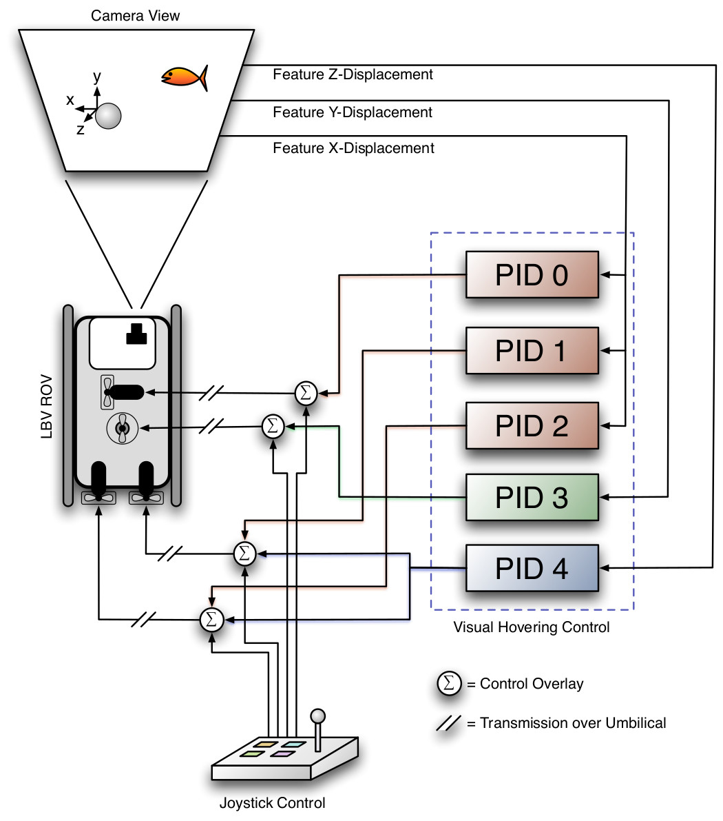
We tested our approach using the small-class LBV150 ROV by Seabotix. The vehicle is normally controlled by a hand controller which is connected to the surface power supply. The hand controller uses a RS232 signal to communicate with the ROV. The signal is modulated onto the DC power inside the surface power supply and is demodulated onboard the ROV. In order to be able to control the vehicle with a computer, the protocol sent by the hand controller was reimplemented such that the computer could completely replace the manual control. As the hand controller has only a control frequency of just 2Hz, the computer is also bound to this rather slow control frequency. In our setup, the ROV is controlled via a software running on a standard desktop computer or notebook. The software displays information of the actual system state, e.g. the actual thrust on the different thrusters, and has an integrated video window which displays the video feed of the ROV. The hover control can be activated/deactivated at any time with the respective button on a joystick. When the hover control is activated, the system selects a number of salient features around the center of the actual video frame using our vision-based algorithm. Subsequently this set of features is tracked by the Lucas-Kanade optical flow until the hover control is deactivated again. While the hover control is activated, the response of the ROV to the relative movements detected by the vision system can be specified due to five PID controllers (Fig. 1a). The PID controllers are highly parameterized to be adaptable to different vehicle and thruster types. For example, the forward thrusters on the LBV have a preferential direction and thus the output of the correspondent PID controllers is asymmetric.
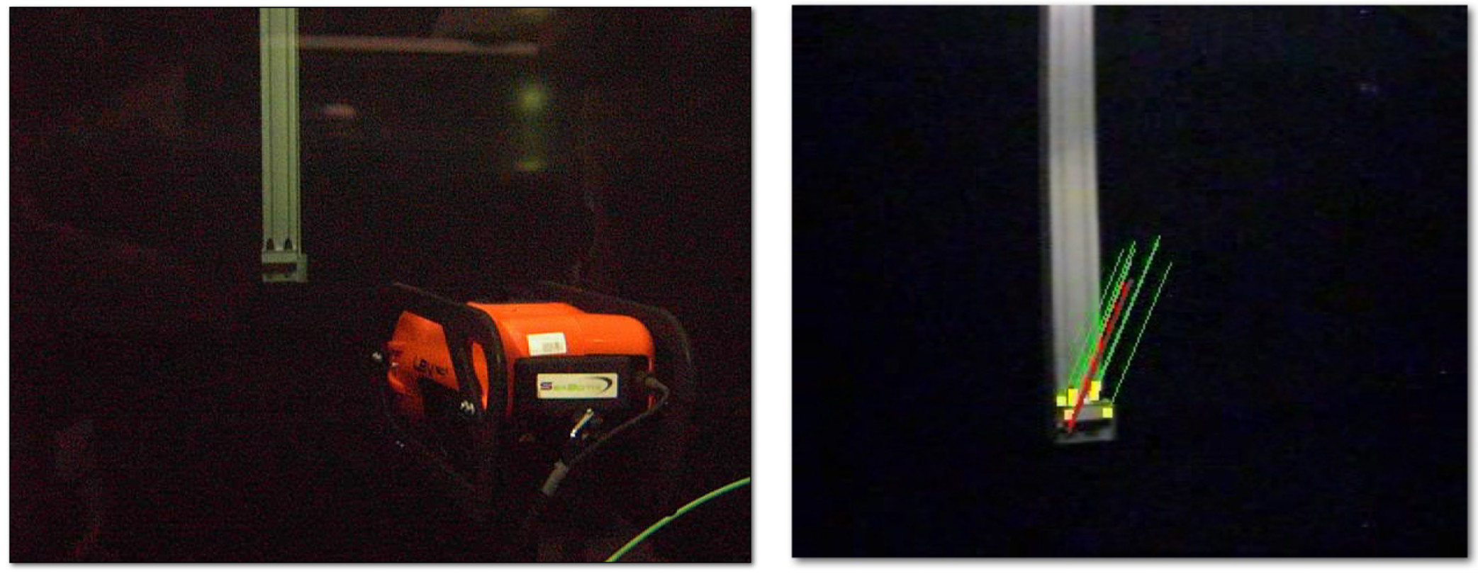
We tested the system in our underwater testbed. The testbed consists of a 25m³ tank spanned by a 3D gantry crane. The gantry crane allows an object to be precisely moved in all 3 dimensions inside the tank with speeds up to 5 meters per second. To test the hover control, the LBV is positioned manually in front of the tip of the gantry crane. As the tip is now in the center of the video image, the features which are selected after the activation of the hover control, usually belong to the tip of the gantry crane. In this situation, the ROV is locked onto the tip of the crane (Fig. 1b). As long as the hover control is activated, the ROV will follow the movements of the gantry crane. Despite the low control frequency the system was able to keep its relative position surprisingly well for periods of up to 30+ minutes.
References
1
,
A Robust Vision Based Hover Control for ROV,
In: Proceedings of OCEANS ’08 (MTS) / IEEE KOBE-TECHNO-OCEAN ’08. IEEE, 2008,
[pdf|doi|bibtex]