

ROV-based manipulators are one of the few possibilities to manipulate objects in the deep sea environment. With increasing demand for facilities and structures in depths beyond the access of human divers and the increasing complexity of such structures, the challenges and applications for manipulator systems are steadily increasing. In order to match these requirements either new manipulation paradigms or novel control systems are imperative. Within the C-Manipulator research project we explored ways to improve and augment existing manipulator technology through the use of new human-machine interfaces and computer-assisted control approaches.
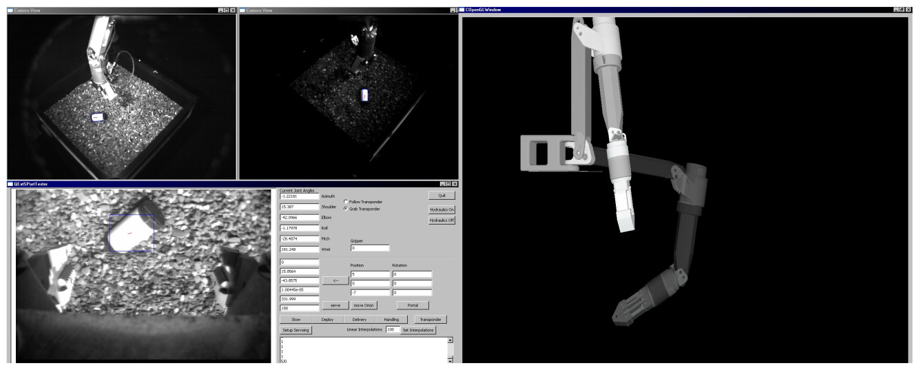
In [1] we present a system for semi-autonomous picking and placing of objects for the Orion 7P manipulator by Schilling robotics. Normally, the Orion 7P is controlled by direct angular input using an input device that mimics the morphology of the robotic arm. This means that the robot is controlled like a puppet and all manipulation tasks have to be performed manually in angular (not euclidean!) space. In addition, the manipulator is typically mounted to a non-stationary ROV, i.e., the robot base can and will move during operation. As a result, controlling such a manipulator is a demanding task that requires highly skilled operators. We augmented this existing system with a computer-assisted control interface that provides three camera views of the workspace as well as a 3D rendering of the current and future state of the robotic arm. In addition, we provide a semi-autonomous pick and place function. To pick up an object the operator can select this object in one of the camera views. The system will then calculate its location in space using a stereoscopic vision approach, guide the manipulator towards that location using visual servoing, pick up the object, and store it in a predetermined storage location. Conversely, placing an object requires the operator to mark the placement location in one of the camera views. The system will then retrieve the object from the storage location and place it as requested.
High-Precision Position Control
Industrially available deep-sea manipulators like the Orion 7P are build to be highly reliable and tough. However, high precision manipulation as it would be needed to, e.g., automate plugging of cable connections, is poorly supported by these systems. In [2] we present a computer-based control approach which increases the effective precision of such systems by nearly an order of magnitude without any physical changes to the manipulation system. This allows a completely new range of tasks to be executed with certainties usually only attainable with industrial automation robots (which in turn are unsuitable for the underwater realm) or experimental, electric underwater manipulators, which do not meet the speed, reliability and strength requirements of underwater intervention missions.
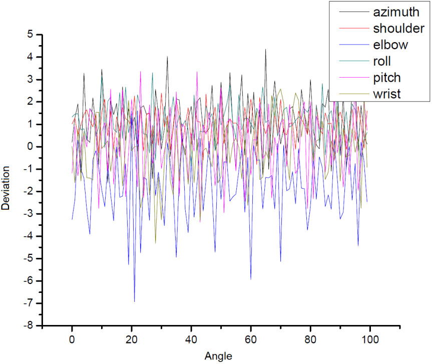
The Orion 7P provides a microcontroller-based position controller for all joints, which regulates the valves in such way that the actuators reach a desired encoder position. This encoder position can be treated as direct measurement of the actuator’s current position, and lies in the rage of 0 − 4096. An ideal controller would always reach exactly the desired encoder position, without any overshoot or deviation. After analysis of the Orion 7Ps controller, it became apparent that it utilizes a linear position controller for each joint. It shows considerable deviation in the magnitude of 130 encoder steps, with both overshoots and undershoots depending on the movement direction. These 3% encoder deviation would mean a maximum joint deviation of 3.6 degrees in the azimuth joint if the actuator-joint relationship was linear, but considering the non-linear relationship this even rises to 4.2 degrees of joint deviation in the worst case. For the other joints these values are in the same order of magnitude.
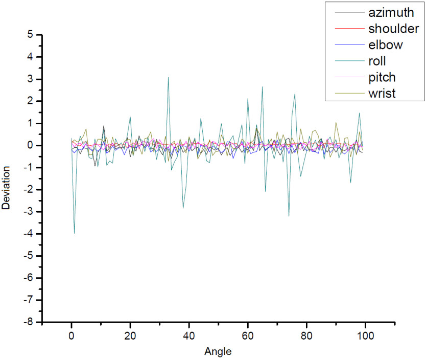
In order to increase precision we added two additional control layers: an adaptive speed control layer and a second position control layer. The second position control layer has the desired sub-degree precision. The idea is to use the adaptive speed controller in order to allow very slow, precise movements. Since the final aim is to reach specific positions, the second position controller manages this speed controller to achieve the desired high position precision. The speed controller uses a simple trick: Instead of giving one position to the Orion controller, it sends a new position at each controller iteration (running at the Orion controller frequency of 12.5Hz). Since the movements achieved this way are very small, the Orion controller does not apply any ramps to them, but tries to reach them directly. This results in the Orion controller staying shortly behind the speed controller, which gives a new position before the Orion controller reached the previous position. By varying the size of the gap between the reached position and the sent position, the speed can be selected. Figure 2 shows the increased precision that we could achieve by this method. A drawback of the proposed system is its manipulation speed, which can be rather slow in the very high precision modes. Since there is a natural trade-off between speed and precision, this was addressed by automatically controlling the precision: If fast movement is required, the system automatically reduces its precision, and vice versa. This way operating the manipulator feels very natural for human operators using the computer control.
Motion Compensation
ROV-based manipulator systems suffer the problem of two coupled high-DOF systems: the 6 DOF ROV platform plus the (usual) 4-7 DOF manipulator. In a Heavy-Workclass ROV these two systems typically are operated by two individual operators, one steering the ROV and the second performing the teleoperated manipulation. One of the main tasks of the ROV operator is keeping the ROV as steady as possible to avoid additional movement of the manipulator, especially the end-effector of the manipulator, since this is the interaction point with the environment. From a manipulation perspective these added 6 DOF severely aggravate the manipulation problem, and need to be kept as small as possible. This problem may be addressed in two different ways: either by keeping the ROV’s position as stable as possible using station keeping algorithms or by recognizing the ROV movement and compensating the manipulator’s end-effector position accordingly. The former has been topic of intense research, and a number of well-performing methods exist. ROV motion compensation using the manipulator is scarcely seen in underwater systems, since manipulator systems are usually directly teleoperated with little to no computer control, making automated compensation algorithms difficult to implement. In principle, such algorithms should outperform station-keeping algorithms, since manipulators have generally more dynamic movement capabilities than ROVs.
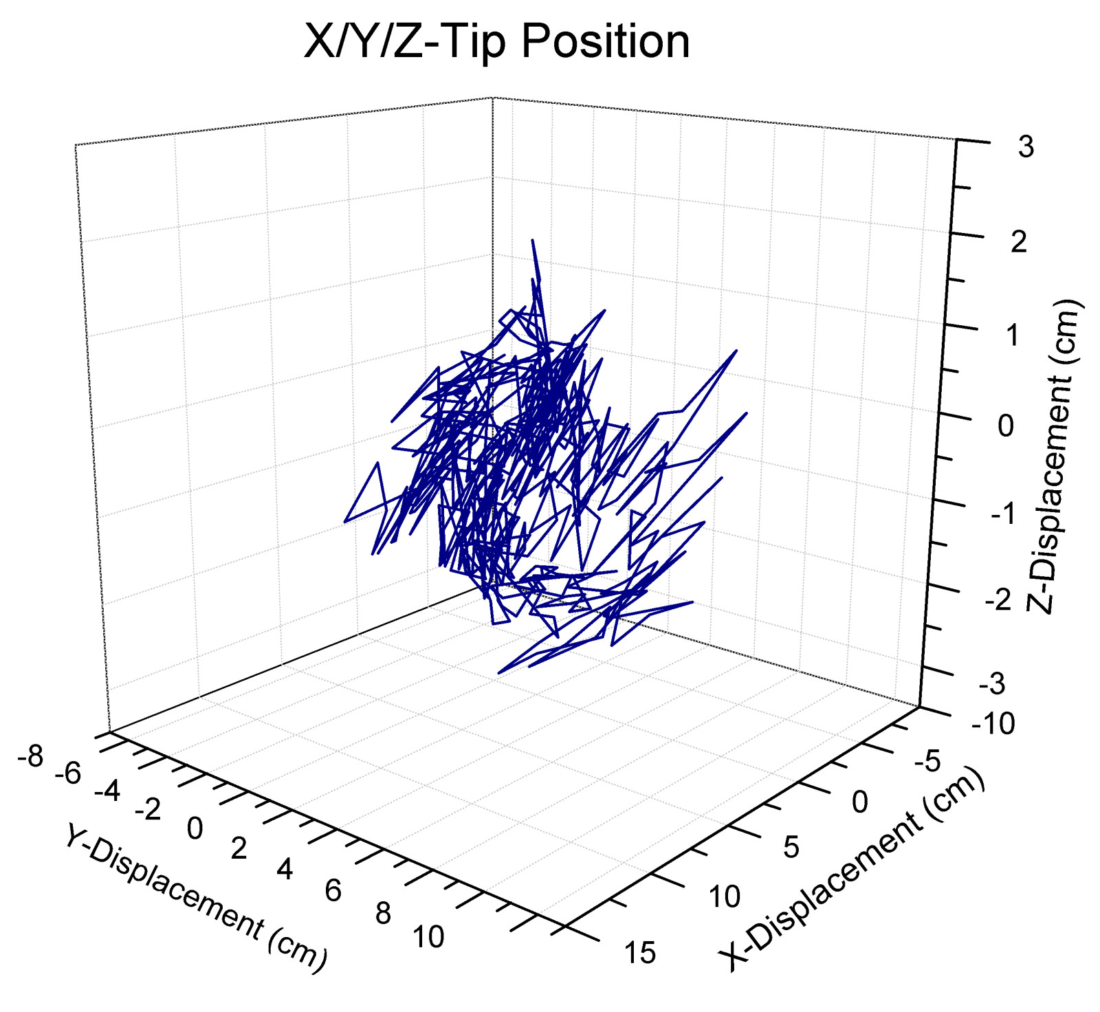
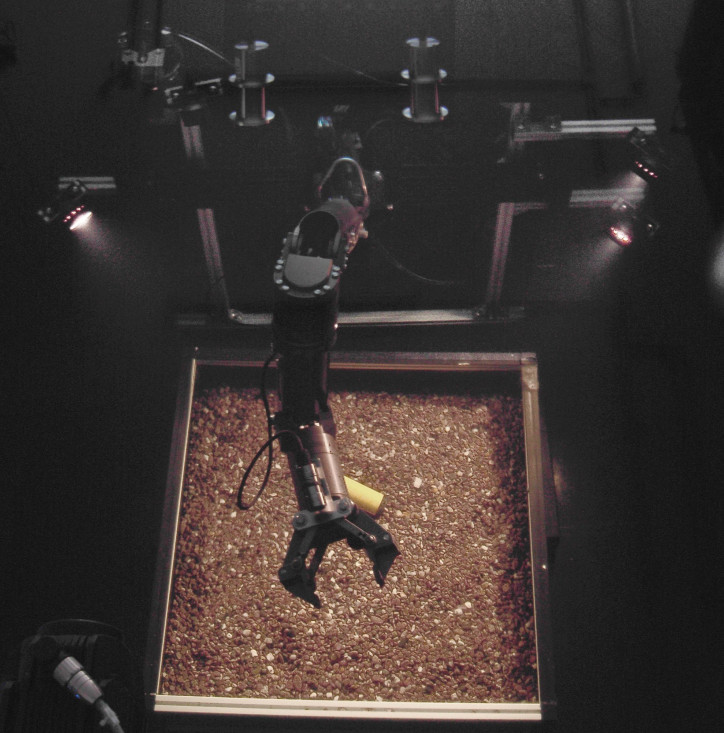
In [3] we demonstrate a ROV motion compensation approach that is realtime capable. The compensation algorithm can be divided into three discrete parts: prediction of vehicle movement, calculation of manipulator compensation movement and execution of the compensation movement with the manipulator. We verified our approach by conducting a number of experiments in our underwater testbed using a hardware ROV simulator. It consists of a 3d gantry crane installed over a 20m³ water basin. Attached to this gantry crane is the Orion 7P underwater manipulator, a number of cameras, light spots and other instruments commonly found on work-class ROV systems. The setup tries to resemble the front section of such a ROV, which can be positioned with high accuracy in all three transational directions by the gantry crane. The experiments involved moving the gantry crane in a sinuoid trajectory resembling ROV movement. The sinoid trajectory can be considered as a ’worst-case’ scenario, due to the constant acceleration and decelration of the overall system. Movement radii between 0 and 20 cm with speeds of 2-20 cm/s were used. The gantry crane is able to move at much higher speeds, but such movements seem inadequate for the selected scenarios, where speeds below 10 cm/s are expected. Figure 3 illustrates the resulting end-effector displacements during movement compensation.
References
1
,
Robust Vision-Based Semi-Autonomous Underwater Manipulation,
In: The 10th International Conference on Intelligent Autonomous Systems. IOS Press, pp. 308–315, 2008,
[pdf|doi|bibtex]
2
,
A Multi-Layered Controller Approach for High Precision End-Effector Control of Hydraulic Underwater Manipulator Systems,
In: OCEANS MTS/IEEE Conference (OCEANS-09). o.A., 2009,
[pdf|doi|bibtex]
3
,
Realtime motion compensation for ROV-based teleoperated underwater manipulators,
In: OCEANS 2009 - EUROPE, 2009,
[pdf|doi|bibtex]