

The dc-manipulator systems that are typically used on small- or middle-class ROVs come without any sensory systems which could provide position or speed feedback. They are intended to be used directly by a human operator who controls the robotic arm just by visual inspection. However, if such a manipulator system has to be controlled by a computer to manipulate things autonomously or to provide computer-assistance to the operator, some information about the actual speed and position of the joints is needed. Furthermore, information about actual speed and power can be used to estimate the current force applied by the manipulator and thus can be used to manipulate objects very carefully.
Even though it seems to be possible to refit a robotic arm with proper position or speed sensors on every joint, this procedure would be quite complicated, expensive and errorprone. In case of an underwater system additional complications with respect to sealing issues are to be expected. In [1] we present a solution to this problem by using the dc-motors of the robotic arm themselves as sensors. This method, called ”Back EMF control”, uses the current induced by the motors to measure the actual rotating speed of the motor shaft and allows for precise control of the motor speed and, by integration, control of the particular joint position. In Addition, by monitoring the needed power to provide a certain speed, an obstruction of the robotic arm or an object inside the gripper can be detected. This kind of measurement is inherently safe and robust, as it directly uses the motors as sensors. Only when a motor fails, the sensor fails too and in such a situation, the sensor failure is the least problem. We demonstrate this technique on the 123 DC-Manipulator by sub-Atlantic.
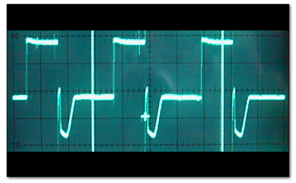
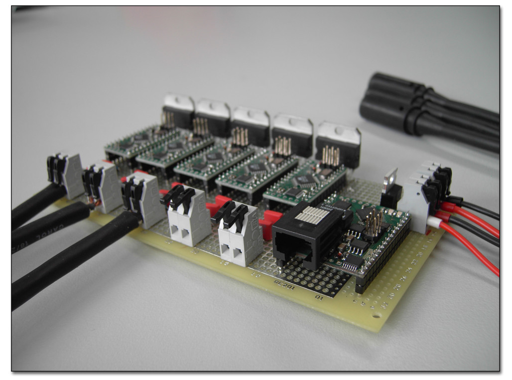
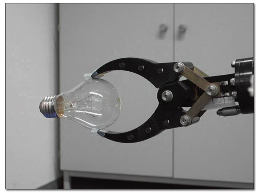
Figure 1a depicts the voltage characteristic at the motor terminals while a PWM signal with 33% duty cycle is applied. After the high phase of the PWM signal, the spike caused by the motor coils is clearly visible. Due to this spike, the measurement of the back EMF schould take place as late as possible during the subsequent low phase. The late measurement ensures the least interference with the spike at the beginning of the low phase. In addition, it allows for a duty cycle as large as possible. As we need at least some low phase duration for our measurement, it is obvious that a 100% duty cycle of the PWM signal is not possible when using back EMF control. In our setup the maximum usable duty cycle was 75%. To compensate for the loss of power caused by this restriction, a higher input voltage can be used, e.g. a 24 volt system would be driven with a 32 volt input if the maximum usable duty cycle is 75%.
The electronics used to demonstrate the back EMF control approach is shown in figure 1b. The prototype board supports the back EMF control of up to 5 dc-motors. For each motor a separate microcontroller unit reads the back EMF voltage and generates the PWM signal send to the motor driver IC. The used microcontroller on each unit is an ATMEGA168 by Atmel and the motor driver IC is a L6203 by STMicroelectronics. These joint control modules are connected via an I2C bus to a central microcontroller module with ethernet capabilities as communication interface.
The back EMF signal measured has relatively low noise, which allows the speed to be controlled very precisely. This holds true even for very low speeds. In our experiments the skid of the spindle drive could be moved as slow as 1.5mm per second. This speed control enables the dc-manipulator to carry out very precise manipulation tasks which were not possible before to such an extent. Furthermore, with the information of the actual speed and the actual PWM duty cycle of a joint it can be estimated if the joint is in some way obstructed. Such an estimation is especially important for the gripper, as it enables the system to grasp very fragile things without damaging them. In addition, this information can be used to inform the operator of the manipulator of a possible degradation of a joint, e.g. caused by some fouling on the spindle or motor shaft. Thus protecting the manipulator system at an early stage and reducing the risk of a complete breakdown of that particular joint. As an example for the sensitiveness of this back EMF based force control we were able to grip, among other sensitive objects, a lightbulb with our system (fig. 1c).
References
1
,
Sensorless Computer Control of an Underwater DC Manipulator,
In: Proceedings of OCEANS ’08 (MTS) / IEEE KOBE-TECHNO-OCEAN ’08. IEEE, 2008,
[pdf|doi|bibtex]