

Having a balcony with a lot of flowers and plants is a nice thing. However, if you need to travel regularly, keeping the plants watered can be somewhat of a challenge. For this reason, I wanted to automate the watering of my balcony plants.
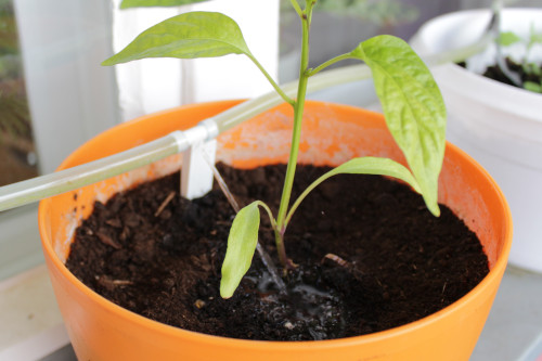
I used 6mm transparent PVC tubing and 3D printed a set of custom nozzles (Fig. 1). The nozzles have different hole diameters depending on the expected water needs of the particular plant. I made sure that the sum of the nozzle cross-sectional areas stayed below the cross-sectional area of the tubing to ensure sufficient water pressure. There are four independent water circuits to address different overall watering needs depending on the plant’s position, i.e., depending on the amount of sunlight they are exposed to.
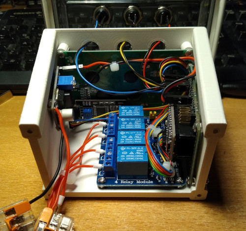
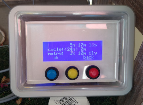
The first version of the system (Fig. 2) was controlled by a microcontroller that was housed in a casing outside on the balcony. Connected to the controller were four moisture sensors to estimate the needed amount of water in the four water circuits. Each water circuit was supplied by a low voltage pump that was submerged in a 20 liter water canister. The system worked sufficiently well for one season. After the winter, I checked the system. One pump was stuck and another one was completely dead. Similarly, one of the moisture sensors gave erroneous readings. Given the state of the system I had to choose between repair or redesign. I chose the latter since I wanted to improve on a number of things. The water tank I used had two major issues: during peak summer times it barely held enough water for one week and the submersible pumps were not easily accessible (which is one reason why I left the pumps outside during winter). Regarding the moisture sensors I realized that they were not really needed. It would be sufficient if I could control the amount of water depending on the expected weather for the coming weeks. Lastly, I got annoyed by the untidiness of the visible PVC tubing of the system.
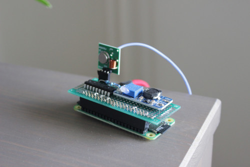
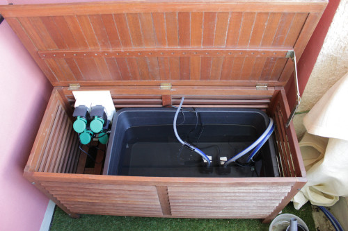
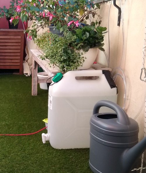
The second version of the system was an exercise in complexity reduction (Fig. 2). I used a garden storage chest to house a simple, open 60 liter water tank. As pumps I decided to use robust and cheap submersible fountain pumps running directly on mains voltage. To control the pumps I opted for remote controlled power outlets. I decoded their control signals via a 433Mhz receiver module and replicate these signals using a simple 433Mhz sender module. Instead of a microcontroller I use a Raspberry Pi Zero W. To achieve a higher RF output I drive the sender module with 12V from a DC-DC step-up converter and use a simple darlington array to interface with the GPIO pins of the Raspberry Pi. I wrote a small C program to handle the IO and generate the required bit patterns to control the power outlets. The “high-lever” scheduling of the watering cycle is done in a very minimalistic fashion. Every hour, a cronjob executes a script that downloads a watering schedule from my web server. It then parses the schedule and if the time matches, it executes a watering cycle. If there is not internet connection, the script just uses the latest schedule it downloaded before.
This simple setup allows me to adjust the watering schedule from everywhere. I just need to ssh on my server and edit a simple text file. This may seem quite rudimentary to many, but it is actually very versatile, fast and comfortable to use.